Why do custom battery packs require nickel welding strips? The answer begins at the cell connection. A strip must carry current between cells while staying firmly attached during heat, vibration, and repeated use. Nickel is commonly selected because it is conductive, weldable, and resistant to corrosion. Yet the right choice depends on the design. Strip thickness, width, cell layout, current demand, and welding settings all matter.
Battery researcher Dr. Jeff Dahn’s work focuses on battery materials and performance. The following is a paraphrase of an engineering principle, not a verified direct quotation: “Reliable battery performance depends on careful choices throughout the cell and pack design.” That matters at the joints. A strip that is too thin may heat under load; an oversized strip can add cost and complicate assembly. A clean weld should hold securely without damaging the cell’s terminal. Small details count.
For builders, nickel strips can offer a practical balance of conductivity, weldability, and durability. But “nickel” does not automatically mean pure nickel: nickel-plated steel may look similar and behave differently. Check the material specification, measure the strip, and test sample welds before assembling a pack. This is not glamorous work. It is easy to overlook. A careful design review can catch weak connections early, though no single strip specification suits every custom pack.
How Cell Layout and Series-Parallel Links Define Pack Interconnect Needs
Why Do Custom Battery Packs Require Nickel Welding Strips?
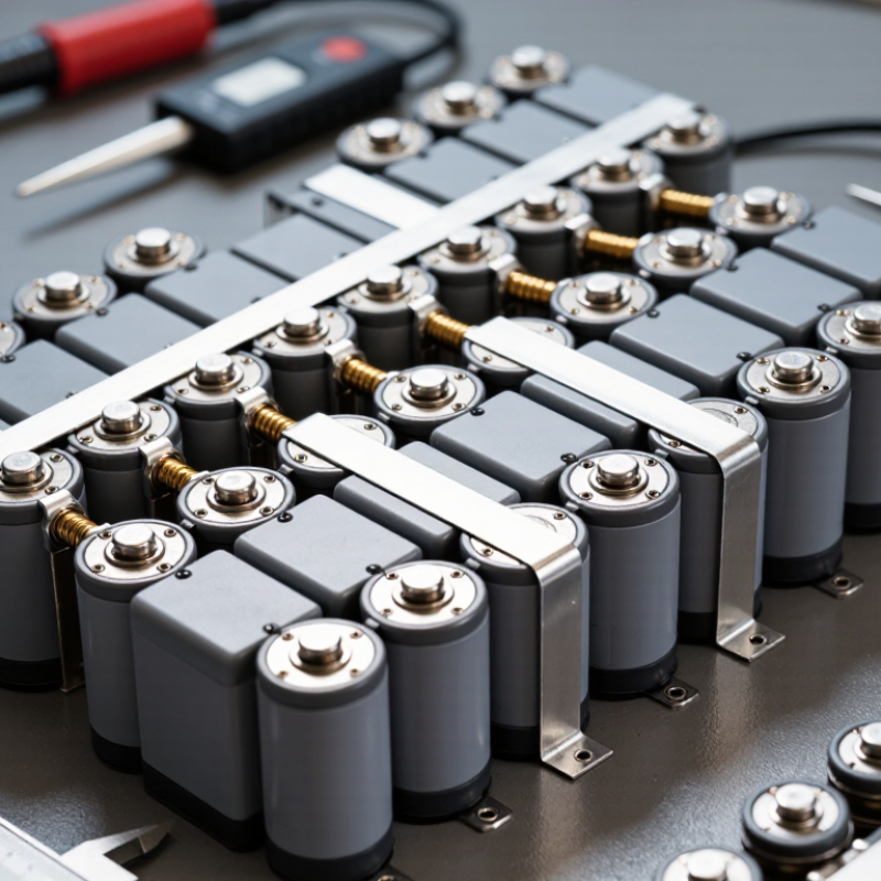
In a custom battery pack, cell placement determines where current must travel. The series links connect one group’s positive end to the next group’s negative end, raising voltage. Parallel links join matching terminals, increasing available capacity and current. A 4S3P layout, for example, needs connections between four series groups and links among three cells in each group. Layout matters. These paths shape the number, length, and position of the interconnects.
Nickel strips are commonly used because they can be resistance-welded to cell terminals and shaped to fit compact layouts. Their width, thickness, and route affect electrical resistance and heat. A long, narrow strip may warm more under load than a short, wide one. Resistance adds up. Designers need to assess expected current, connection geometry, and the cell manufacturer’s limits rather than choosing strip dimensions by appearance alone.
The weld pattern also matters. Poorly placed welds can weaken a joint, while crowded links may complicate assembly or inspection. In practice, a layout that looks neat on a drawing can still leave uneven current paths between parallel cells. That detail is easy to underestimate. Nickel is not automatically the best choice for every pack; material and strip dimensions depend on the application, welding process, and thermal conditions. Prototype measurements can reveal problems that calculations miss.
Why nickel strips matter: Parallel links join cells within each group, while series links connect one group to the next. The counts shown are derived from each S×P configuration; the required strip layout depends on cell arrangement and weld design.
Why Nickel’s 6.99 μΩ·cm Resistivity Differs From Copper’s 1.68 at 20°C
Why Do Custom Battery Packs Require Nickel Welding Strips?
At 20°C, pure nickel has a resistivity of 6.99 μΩ·cm, compared with copper’s 1.68 μΩ·cm. For strips with identical dimensions, nickel therefore has about four times the electrical resistance. That difference matters: under load, resistance produces heat and voltage drop. A designer cannot treat nickel and copper as interchangeable.
Nickel remains common because it can form reliable spot-welded connections to many cylindrical cell terminals. Its surface and mechanical behavior suit this joining method, while copper’s high conductivity quickly carries heat away from the weld area. Copper can still work, but often needs different equipment or joining methods. The detail is easy to miss. Strip thickness, width, weld settings, and contact quality all affect the result.
In a custom pack, the choice should follow the current path, not habit. A narrow nickel strip may run hotter than expected during sustained high current. Wider or thicker material can reduce resistance, but it also changes weld behavior and pack layout. Check the actual strip composition, too: nickel-plated steel does not conduct like pure nickel. I have seen material names used loosely, and that deserves a second look. Test representative joints under realistic loads and temperatures before settling on a design.
How Strip Width, Thickness, and Joint Count Affect Resistance and Heating
Nickel welding strips provide a controlled path between cells, but their dimensions influence resistance directly. ASM International’s ASM Handbook, Volume 2, lists pure nickel’s electrical resistivity at about 6.99 μΩ·cm near room temperature. In practice, strip resistance follows R = ρL/A: longer paths raise resistance, while greater cross-sectional area lowers it. A wider strip can help. So can a thicker one. Yet narrow cell spacing or tight bends may limit both choices.
Joint count matters, too. Each weld interface can add contact resistance, especially when pressure, surface condition, or weld quality varies. In a series current path, more joints mean more opportunities for localized voltage drop and I²R heating. Parallel current paths can share the load, but uneven welds may prevent equal sharing. The U.S. Department of Energy’s battery manufacturing research emphasizes process consistency because electrode and connection variation affects cell performance; the same practical caution applies to pack interconnects. A simple strip calculation is useful, but it cannot fully predict a real pack. Weld geometry, pulse settings, and measured joint resistance still matter. Check temperatures under representative load, not just at idle.
Why Do Custom Battery Packs Require Nickel Welding Strips? — How Strip Width, Thickness, and Joint Count Affect Resistance and Heating
| Strip Width |
Strip Thickness |
Current Path Length |
Weld Interfaces |
Calculated Strip Resistance |
Assumed Joint Resistance |
Estimated Total Resistance |
Power at 10 A |
| 5 mm |
0.15 mm |
20 mm |
2 |
1.864 mΩ |
0.400 mΩ |
2.264 mΩ |
0.226 W |
| 5 mm |
0.15 mm |
20 mm |
4 |
1.864 mΩ |
0.800 mΩ |
2.664 mΩ |
0.266 W |
| 5 mm |
0.20 mm |
20 mm |
2 |
1.398 mΩ |
0.400 mΩ |
1.798 mΩ |
0.180 W |
| 8 mm |
0.20 mm |
20 mm |
2 |
0.874 mΩ |
0.400 mΩ |
1.274 mΩ |
0.127 W |
| 8 mm |
0.20 mm |
20 mm |
4 |
0.874 mΩ |
0.800 mΩ |
1.674 mΩ |
0.167 W |
| 10 mm |
0.20 mm |
20 mm |
2 |
0.699 mΩ |
0.400 mΩ |
1.099 mΩ |
0.110 W |
| 10 mm |
0.30 mm |
20 mm |
2 |
0.466 mΩ |
0.400 mΩ |
0.866 mΩ |
0.087 W |
Calculation basis: Illustrative values for a 20 mm current path in pure nickel at approximately 20°C, using a resistivity of 6.99 × 10⁻⁸ Ω·m. Strip resistance is calculated as R = ρL/A; power is calculated as P = I²R at 10 A. For comparison only, each weld interface is assigned an assumed resistance of 0.20 mΩ. Actual weld resistance depends on materials, surface condition, weld process, and joint quality, and should be measured in the finished pack. These figures estimate electrical power dissipation, not operating temperature.
Why Resistance Spot Welding Suits Cell Tabs Better Than Soldering
Custom battery packs use nickel welding strips because they provide a consistent connection between cells and the pack’s conductors. For many cylindrical cells, resistance spot welding joins a strip to a cell tab with brief, localized heat. The cell still warms, but the process can limit heat exposure compared with applying a soldering iron directly to the terminal.
That difference matters. Soldering may require longer contact, and heat can travel into a cell’s seal or internal components. Some terminal surfaces also resist solder, making the bond less dependable. Spot welding avoids relying on solder adhesion and can create repeatable joints when electrode pressure, pulse energy, and strip material are properly controlled. A clean-looking joint can still be weak.
Material choice needs care. Pure nickel and nickel-plated steel are not interchangeable in every design; conductivity, current demand, corrosion resistance, and weldability all matter. An experienced builder checks the weld process on test pieces before assembling cells, then inspects joints for consistent marks and adequate strength. Pull testing can reveal problems that appearance alone misses. It is not magic. Poor settings can damage a terminal or leave a fragile bond, so the welding method and strip thickness should match the cell and pack design.
How IEC 62133-2:2017 Safety Testing Makes Weld Integrity Matter
A nickel strip is more than a bridge between cells. It carries current while holding connections together through handling and use. In a custom pack, a weak weld can raise resistance, create a hot spot, or interrupt the circuit. The defect may look tiny. Its effects may not.
IEC 62133-2:2017 sets safety requirements and test methods for portable sealed secondary lithium cells and batteries. Depending on the battery design and applicable test, evaluations can expose packs to stresses such as vibration, shock, or electrical abuse. These conditions make sound connections important: a poor weld may loosen, heat up, or behave differently under load. The standard does not prescribe one nickel-strip thickness or welding recipe. Designers must validate the actual pack configuration.
Good practice combines controlled weld settings with inspection and testing. A technician might check consistent weld marks, examine sample joints, and measure connection resistance. Pull tests can reveal weak bonds, though they cannot represent every service condition. There is no perfect visual shortcut. Even a neat weld can hide a weak joint, so test results and process records matter. Engineers should review failures honestly and adjust the design or process when evidence points to a problem.
Conclusion
Custom battery packs use nickel welding strips to connect cells in carefully planned series and parallel layouts. The arrangement determines where current must flow, how many links are needed, and how much electrical and mechanical stress each connection may experience. Nickel has a higher resistivity than copper—about 6.99 μΩ·cm compared with 1.68 μΩ·cm at 20°C—so strip dimensions and connection design matter. Greater width or thickness can reduce resistance, while each joint adds another point where resistance and heat may develop. These considerations help explain why do custom battery packs require nickel welding strips: the interconnects must suit the pack’s current paths and cell layout.
Resistance spot welding is often better suited to cell tabs than soldering because it can make localized joints without broadly heating the cells. Consistent weld quality is important for dependable electrical contact and pack durability. Safety testing under IEC 62133-2:2017 makes weld integrity especially relevant, since weak or inconsistent connections can affect a pack’s ability to perform safely under testing and use.

 Nuwon Energy