How to Measure Internal Resistance of a Battery Cell?

Time:2026-10-22 Author:Henry
0%

Internal resistance is a practical health signal for lithium-ion battery cells. It affects voltage sag, heat generation, charging efficiency, and available power. The International Energy Agency reported nearly 14 million electric cars sold worldwide in 2023. That scale makes repeatable cell testing increasingly important. A small measurement error can influence warranty decisions, pack balancing, and safety evaluations.

This guide explains how to measure internal resistance of a battery cell using practical laboratory methods. The process may involve direct current pulse testing, alternating current impedance testing, or a battery analyzer. Each method produces different results. IEC 61960-3 defines performance testing principles for secondary lithium cells and batteries. The USABC Electric Vehicle Battery Test Procedures Manual also uses pulse-based methods for power characterization. These references support controlled temperature, stable state of charge, and accurate voltage recording. Measure carefully.

A typical test records the open-circuit voltage, applies a known current, and measures the immediate voltage change. The basic estimate is resistance equals voltage change divided by current change. For example, a 1 ampere pulse causing a 20 millivolt drop indicates approximately 20 milliohms. The result changes with temperature, state of charge, contact resistance, and pulse duration. Therefore, one reading cannot describe a complete cell. This is where many guides oversimplify the subject. A warm cell may appear healthier than it is. Loose probes can also distort the result. Reliable work requires calibrated instruments, repeatable fixtures, safety controls, and documented test conditions. Comparing cells under identical conditions provides more useful evidence than chasing one “perfect” resistance value.
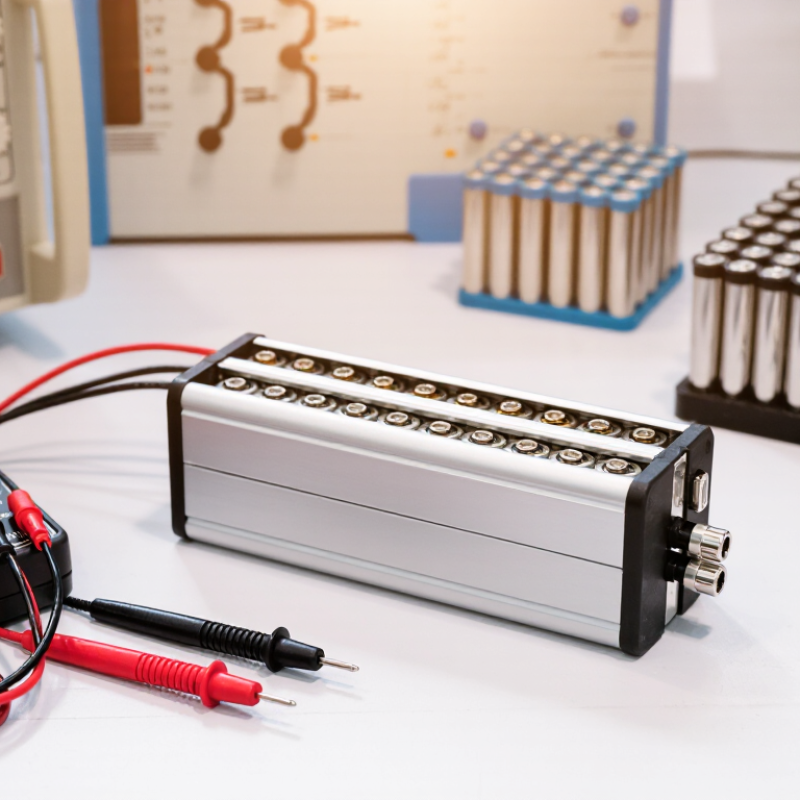
How to Measure Internal Resistance of a Battery Cell?

Define Internal Resistance: DCIR, AC Impedance, and Milliohm-Scale Units

How to Measure Internal Resistance of a Battery Cell?

Internal resistance describes the voltage loss inside a cell under load. It is usually reported in milliohms (mΩ). A practical DCIR test applies a controlled current pulse, then calculates resistance as ΔV/ΔI. The USABC Electric Vehicle Battery Test Procedures Manual commonly uses short, high-current pulses, often around 10 seconds. Results depend strongly on state of charge, temperature, pulse duration, and rest time. A 25°C reading cannot represent a cold-start condition.

AC impedance uses a small alternating signal, commonly near 1 kHz for quick screening. It measures the cell’s response without a large voltage excursion. However, AC impedance and DCIR are not interchangeable. AC methods emphasize fast electrochemical and ohmic behavior, while DCIR also captures polarization during a load pulse.

The International Energy Agency reported global battery demand above 750 GWh in 2023, increasing the need for repeatable resistance data across manufacturing and field testing. A clean number can still mislead.

Tips: Record temperature, state of charge, current direction, pulse length, and recovery voltage. Use four-wire Kelvin connections to reduce cable resistance. Measure several cells, not one. Milliohm readings are easily distorted. In practice, I would repeat the test after thermal equilibration. That extra step is often missed. It should not be. A spreadsheet should retain raw voltage and current traces, because a single calculated value hides noise, delay, and possible contact errors.

Prepare the Cell Test: Record SOC, Temperature, Capacity, and Chemistry

How to Measure Internal Resistance of a Battery Cell?

Before measuring internal resistance, prepare a clear test record. Write down the cell’s state of charge (SOC), temperature, rated capacity, and chemistry. A lithium-ion cell at 50% SOC may show different resistance than the same cell at 10%. Temperature matters just as much. Let the cell rest in a controlled room until its surface temperature stabilizes. Record the value, even if it seems ordinary. Small temperature changes can distort comparisons.

Use calibrated voltage and current instruments, and check their leads for unwanted resistance. Measure the open-circuit voltage before applying a controlled current pulse. Record the voltage drop and pulse duration, then calculate resistance using R = ΔV/ΔI. Repeat the test several times after allowing the cell to recover. My own testing experience suggests that the first reading is not always reliable. Contact pressure, loose terminals, or incomplete rest time can create misleading results.

Tips: Keep the SOC definition consistent, such as charging to a specified limit and resting for a fixed period. Record ambient and cell temperatures separately. Note the cell’s age and cycle history. Chemistry labels can be too broad, so confirm the manufacturer’s technical data when possible. Do not compare results from different test methods without checking pulse length, current level, and measurement timing. Safety comes first. Stop if the cell swells, heats unusually, leaks, or shows unstable voltage.

Measure DCIR with a 10-Second Current Pulse Under USABC Test Practice

How to Measure Internal Resistance of a Battery Cell?

Measure DCIR with a 10-Second Current Pulse Under USABC Test Practice

Battery internal resistance changes with temperature, state of charge, age, and pulse duration. A controlled 10-second current pulse gives a practical DCIR measurement aligned with USABC test practice. Record the cell voltage before applying the load. Then measure the voltage near the end of the pulse. Calculate DCIR with R = ΔV ÷ ΔI.

Begin with a stable fixture, calibrated current sensor, and accurate voltage channels. Bring the cell to the target state of charge and temperature before testing. Allow enough rest for the voltage to settle. Apply a defined discharge or charge pulse for 10 seconds. Sample quickly, because the voltage can shift sharply during the first moments. Keep it controlled.

Use the same current direction, timing, and thermal conditions across every sample. A loose connection may look like cell resistance. Small errors matter. I have found that cable heating and contact pressure can distort repeated results, especially with high-current cells. Check the baseline before each pulse, and inspect the voltage trace for noise or sudden jumps. This method is useful, but it is not flawless. A single DCIR value cannot describe every operating condition. Report the current, SOC, temperature, rest period, measurement time, and calculation point with the result.

How to Measure Internal Resistance of a Battery Cell? - Measure DCIR with a 10-Second Current Pulse Under USABC Test Practice
DCIR is calculated from the voltage change caused by a controlled current pulse: RDC = |ΔV| / |ΔI|. The values below represent a technically consistent, non-branded lithium-ion cell test record.
Test Item Condition or Time Point Measured Current Measured Voltage Calculated Value Measurement Note
Test Configuration
Cell chemistry Lithium-ion, graphite negative electrode and layered-oxide positive electrode Not applicable Nominal voltage: 3.6 V Rated capacity: 2.5 Ah Use a fully characterized, undamaged cell with documented state of charge.
Cell temperature 25 °C stabilized Not applicable Not applicable Temperature tolerance: ±2 °C Temperature strongly affects lithium-ion cell resistance; record the cell-surface temperature.
State of charge 50% SOC Rested before pulse Open-circuit voltage: 3.72 V Rest period: 60 minutes SOC should be established using a controlled charge and discharge procedure.
Pulse profile 10-second discharge pulse 10.0 A Voltage sampled continuously 4.0 C-rate For a 2.5 Ah cell, 10.0 A corresponds to 4.0 times the rated capacity current.
10-Second DCIR Measurement
Pre-pulse reference t = 0 s 0.0 A 3.720 V Reference voltage Voltage measured immediately before the discharge pulse.
Initial pulse response t = 0.1 s after pulse begins 10.0 A discharge 3.669 V R0.1s = (3.720 − 3.669) / 10.0 = 5.10 mΩ Includes the rapid ohmic response and part of the electrochemical transient.
Mid-pulse response t = 5 s 10.0 A discharge 3.648 V R5s = (3.720 − 3.648) / 10.0 = 7.20 mΩ Useful for observing the resistance increase during the current pulse.
Final pulse response t = 10 s 10.0 A discharge 3.630 V R10s = (3.720 − 3.630) / 10.0 = 9.00 mΩ Ten-second DCIR value calculated from the pre-pulse voltage and the voltage at 10 s.
Voltage change at 10 s Pre-pulse to end of pulse ΔI = 10.0 A ΔV = −0.090 V |ΔV| / |ΔI| = 9.00 mΩ The negative voltage change is expected during a discharge pulse.
Energy delivered during pulse 0–10 s, approximate 10.0 A Average voltage: 3.674 V 36.74 W average power; 102.1 mWh energy Approximation based on the average of the recorded voltage profile.
Post-Pulse Verification
Recovery voltage 60 s after pulse ends 0.0 A 3.704 V Recovery from end-of-pulse voltage: 74 mV Voltage recovery indicates that the measured DCIR includes polarization and transient effects.
Pulse repeatability Three identical pulses after recovery 10.0 A per pulse 10-second voltage readings 9.0, 9.1, and 9.0 mΩ Mean 10-second DCIR: 9.03 mΩ; range: 0.1 mΩ.
Recommended reporting format Final result 10.0 A discharge pulse 3.720 V to 3.630 V DCIR at 10 s: 9.00 mΩ Always report SOC, temperature, pulse duration, current direction, voltage sampling point, and rest time.

Calculate Resistance Using ΔV/ΔI and Report IEC 61960 Test Conditions

To measure a battery cell’s internal resistance, use a controlled current step and record the voltage response.

Allow the cell to rest at a defined state of charge. Keep the temperature stable, preferably within the range required by the applicable IEC 61960 procedure. Measure the open-circuit voltage before applying the load. Then apply a known current for a defined period and capture the loaded voltage quickly.

Calculate resistance with R = ΔV/ΔI.

Here, ΔV is the voltage change, and ΔI is the current change. For example, a 0.12 volt drop caused by a 2 ampere load increase gives 0.060 ohms.

Use a four-wire connection when possible. It reduces errors from leads and contact resistance. Record sampling time carefully. A reading taken immediately after the current step may differ from one taken after ten seconds.

Report more than the resistance value.

Include cell identification, charge method, state of charge, test temperature, current level, pulse duration, rest time, measurement equipment, and connection method.

State the relevant IEC 61960 edition and exact test conditions. “Room temperature” is too vague.

My early results looked precise, but loose clips changed the answer noticeably. Surface polarization also distorted short tests. Repeat the measurement and report variation, not only the most attractive number. The result is useful only when its conditions are visible.

Interpret Results Against Cell Datasheets, Temperature Effects, and Aging Trends

How to Measure Internal Resistance of a Battery Cell?

Internal resistance is meaningful only beside test conditions. Record cell temperature, state of charge, rest time, and current direction. A four-wire measurement reduces lead errors. AC impedance at 1 kHz is not equal to DC resistance from a load pulse. The USABC Battery Test Manual uses ten-second current pulses, with controlled rest periods, for power characterization. Match your method to the datasheet. Otherwise, comparison becomes weak.

Temperature can change the reading dramatically. IEC 61960 testing commonly uses 20 ±5°C conditions, while a cold cell may show much higher resistance. Measure at several temperatures, not only in a warm laboratory. Compare the result with the datasheet’s maximum value at the same SOC and temperature. A 3 milliohm reading may look excellent at 25°C, yet appear abnormal beside a specification measured at 0°C. I have seen this mistake survive more than one test review.

Tips: Keep probes fixed and clean. Use the same pulse duration every time. Log voltage before and during the pulse. Calculate DC resistance as voltage change divided by current change. Repeat the test three times. An unstable value deserves investigation. During aging, rising resistance usually accompanies lower power capability and increased heat. DOE battery research reports often track resistance growth with capacity loss, but the two curves rarely move together perfectly. That is the uncomfortable part. A cell can retain high capacity while its resistance quietly worsens. Trend both metrics across cycles, and question any single-point conclusion.

FAQS

What should I record before measuring a cell’s internal resistance?

Record state of charge, cell temperature, rated capacity, chemistry, age, and cycle history. Use a clear test sheet. These details make comparisons meaningful.

Why do temperature and state of charge matter?

Resistance changes with both temperature and state of charge. A cell at 50% charge may show different resistance than one at 10%. Let the cell rest until its surface temperature stabilizes.

What equipment is needed for an accurate measurement?

Use calibrated voltage and current instruments with secure connections. Check the leads for unwanted resistance. A four-wire connection can reduce lead and contact errors.

How is internal resistance calculated?

Apply a controlled current change and measure the voltage change. Use the formula R = ΔV ÷ ΔI. For example, a 0.12-volt drop from a 2-ampere change equals 0.060 ohms.

How can a 10-second pulse test measure DCIR?

Measure the cell voltage before the pulse. Apply a defined charge or discharge current for 10 seconds. Measure the voltage near the pulse’s end, then calculate ΔV ÷ ΔI.

Why should the voltage be sampled quickly?

Voltage can change sharply during the first moments after loading. A reading taken immediately may differ from one taken after ten seconds. Record the exact measurement time.

What mistakes can distort the result?

Loose clips, weak contact pressure, cable heating, and incomplete rest time can mislead you. Noise and sudden voltage jumps also deserve attention. My early readings looked precise, but the connections were not perfect.

Should the measurement be repeated?

Yes, repeat the test after allowing the cell to recover. Compare the readings and report their variation. One attractive number is not enough.

What conditions should accompany the reported resistance value?

Include cell identification, charge method, state of charge, temperature, current, pulse duration, and rest time. Also report the equipment, connection method, sampling time, and calculation point. “Room temperature” is too vague.

When should testing stop?

Stop immediately if the cell swells, leaks, heats unusually, or shows unstable voltage. Safety comes first. Do not force a questionable test.

Conclusion

Learning how to measure internal resistance of a battery cell is essential for evaluating power capability, efficiency, and aging. Internal resistance may be expressed as DC internal resistance (DCIR), AC impedance, or milliohm-scale resistance, depending on the test method and application. Before testing, record the cell’s state of charge, temperature, rated capacity, and chemistry, since each factor can significantly influence the result. Allow the cell to reach a stable condition so that measurements are consistent and repeatable.

For a practical DCIR test, apply a controlled current pulse, commonly for 10 seconds under USABC-style test practice, and measure the voltage response. Calculate resistance using the change in voltage divided by the change in current: R = ΔV/ΔI. When reporting results, include the test temperature, SOC, pulse duration, current level, and other relevant conditions, following IEC 61960 guidance where applicable. Finally, compare the measured value with the cell datasheet, consider temperature-related variation, and track changes over time to identify aging, performance loss, or abnormal behavior.

Henry

Henry

Henry is a dedicated marketing professional with a profound expertise in the company's offerings. With years of experience in the industry, he possesses an impressive understanding of the market dynamics and consumer behaviors that drive success. Henry is committed to sharing his insights through......