Battery systems are moving into vehicles, solar storage, marine equipment, and outdoor automation. The need for reliable protection is growing quickly. The International Energy Agency’s Global EV Outlook 2025 reported that global electric car sales exceeded 17 million in 2024. BloombergNEF also reported a 20% decline in average lithium-ion battery pack prices during 2024, reaching about $115 per kilowatt-hour. More installations mean more exposure to rain, dust, condensation, vibration, and accidental impact.
This guide explains how to design a waterproof battery enclosure for real operating conditions. It connects material selection, sealing geometry, thermal management, pressure equalization, drainage, and service access. IEC 60529 defines IP protection ratings, but an IP rating alone does not guarantee long-term field performance. Testing must consider water jets, immersion, temperature cycling, cable movement, and aging seals. UL Solutions recommends evaluating battery systems through structured safety testing, including abnormal operating conditions and thermal events. Protection is not only about keeping water out.
Small details matter. A sharp enclosure edge can cut a gasket. A poorly supported cable can pull water through a gland. A cold night can create internal condensation after a hot day. A gasket may look perfect. It can still fail. This guide therefore examines practical design choices, test methods, and common weaknesses before production begins. Some recommendations require adaptation because battery chemistry, installation location, and maintenance access vary. Use this information with qualified engineers and applicable regional standards.
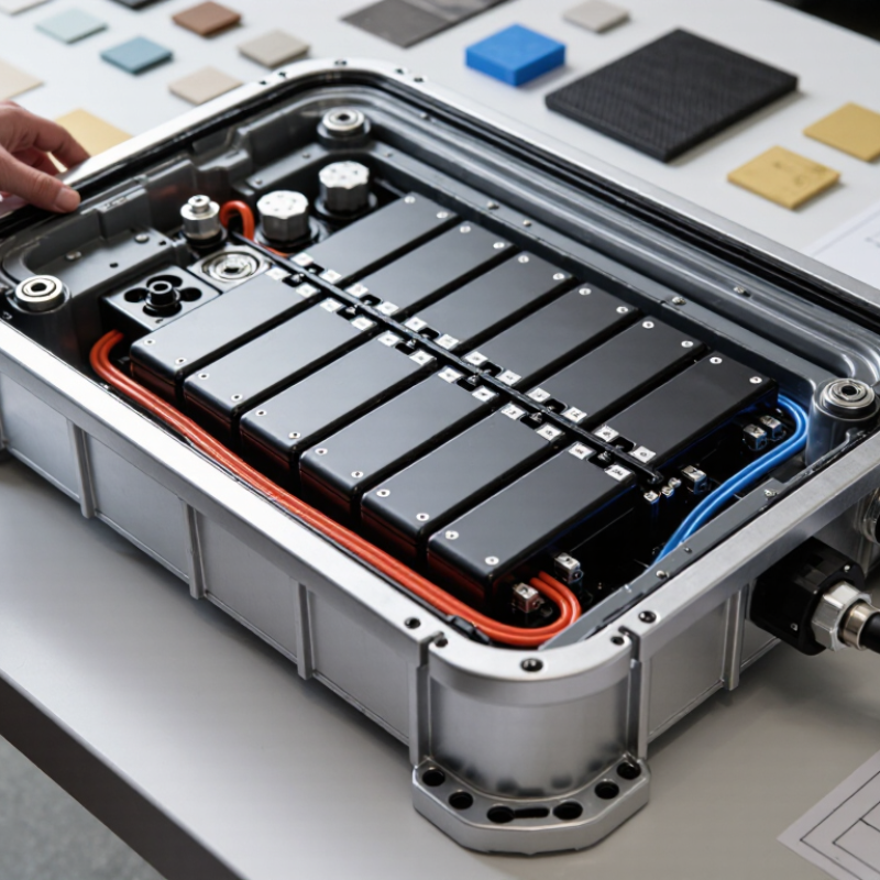
For a 2026 waterproof battery enclosure, define the ingress target before selecting seals or materials. IEC 60529:2013 classifies IP67 as dust-tight protection plus temporary immersion. During the IPX7 test, the enclosure is submerged for 30 minutes, with its lowest point approximately one metre below water.
IP68 demands more careful specification. IEC 60529:2013 defines the second digit as protection against continuous immersion, but it does not set one universal depth or duration. The manufacturer and user must agree on those conditions. For example, a design may require two metres for 60 minutes, while another needs ten metres for 24 hours. That difference changes wall thickness, vent design, connector selection, and pressure testing.
Field experience shows that a successful IP67 test can still hide weaknesses. A gasket may seal at room temperature, then leak after battery heat cycles. Compression matters. So does enclosure distortion. Design reviews should record gasket compression, torque values, cable-entry dimensions, and test-water temperature. IEC 60529 also warns that test results represent defined laboratory conditions, not every outdoor exposure. Salt spray, vibration, condensation, and repeated pressure changes need separate validation.
I would not treat IP68 as automatically “better” without a written immersion profile. That assumption is convenient, but incomplete.
Battery enclosure material selection should begin with fire behavior, not appearance. The UL 94 V-0 classification requires short afterflame times and no flaming drips that ignite cotton. Each tested specimen must stop flaming within ten seconds. The five-specimen total cannot exceed fifty seconds. These limits matter near terminals, busbars, and damaged insulation.
The NFPA Fire Loss in the United States During 2023 reported about 1.5 million fires and 3,670 civilian fire deaths. Meanwhile, the International Energy Agency’s Global EV Outlook 2024 recorded nearly 14 million electric-car sales in 2023. More batteries mean more demand for dependable containment. A V-0 material can reduce flame spread, but it cannot prevent thermal runaway.
Choose materials that retain strength after repeated heat, vibration, and moisture exposure. Check the exact resin grade, thickness, colorant, and processing method. A thin wall may pass a laboratory test yet deform around a hot cell. That is uncomfortable to admit, but real assemblies are less tidy than test plaques. I would inspect the lid seam carefully. Water can enter through a compressed gasket, then create corrosion or tracking near live conductors. Use drainage paths, controlled venting, and tested cable glands. Validate the finished enclosure with immersion, spray, impact, and thermal cycling tests. The material certificate alone is not enough.
Waterproof battery enclosures must manage pressure, water, dust, and cable movement together. The International Energy Agency reported nearly 14 million electric cars sold globally in 2023, increasing demand for dependable battery protection. Yet many failures begin with small design compromises, not dramatic flooding.
Start with the seal path. Use a continuous gasket around the enclosure, with controlled compression and smooth joining surfaces. Randomly tightening fasteners can distort the lid and create uneven sealing. IEC 60529 testing defines IP ratings, but an IP67 result does not prove long-term field durability. Temperature cycling, vibration, and repeated opening can change gasket performance.
Pressure needs another route. A breathable membrane vent can equalize internal pressure while resisting liquid water. Its airflow rating, hydrophobic layer, and mounting orientation require verification. Cable entries also deserve careful attention. Select grommets or sealed connectors that match cable diameter, bend radius, and strain loads. A cable may pull the seal sideways.
Small leaks matter.
For vehicle applications, ISO 20653 adds road-vehicle protection considerations beyond general IP testing. Test complete assemblies, not only empty housings. Include pressure cycling, salt exposure, condensation, and connector movement. I would also inspect failed samples after testing, because a passed laboratory test can hide weak compression zones. Design reviews should record torque, gasket dimensions, vent placement, and cable-entry tolerances. These details make the result repeatable, although real-world aging remains difficult to predict.
Designing a waterproof battery enclosure requires more than sealing every joint. From −20°C to 60°C, temperature changes affect pressure, gasket performance, and battery chemistry. Use a rigid housing with controlled gasket compression. Add a hydrophobic pressure-equalization vent to reduce stress during rapid heating and cooling. A fully sealed box can trap moisture after assembly.
Manage heat through direct thermal paths from cells to the enclosure. Use thermal pads with stable compression, and keep sensors close to the warmest cell groups. At 60°C, charging should be limited or stopped according to validated battery data. At −20°C, heating may be necessary before charging. Never rely on insulation alone. It can delay heat release.
Condensation deserves practical testing. Place a cold enclosure in warm, humid air, then inspect hidden corners and connector cavities. Use drainage features where water could collect. Choose connectors with positive locking and protected contacts. Fire-resistant internal barriers can slow thermal propagation, but they do not replace monitoring and shutdown controls.
I once saw a sealed prototype pass a short spray test, then fail after repeated temperature cycling. The gasket had taken a permanent set. That result was inconvenient, but useful.
Test with vibration, pressure changes, humidity, salt exposure, and repeated charging cycles. Record leakage, temperature rise, insulation resistance, and sensor accuracy. Design reviews should question every assumption. Water resistance is not battery safety.
A waterproof battery enclosure needs more than a strong gasket. It must survive vibration, temperature changes, pressure differences, and repeated charging. ISO 16750 provides a useful framework for evaluating these vehicle-related environmental stresses. Engineers should define mounting position, temperature range, vibration profile, and exposure time before testing. Otherwise, results may look impressive but remain difficult to reproduce.
IP testing checks protection against dust and water under controlled conditions. The enclosure should be tested after assembly, not only as a separate housing. Inspect cable glands, fasteners, vents, and gasket compression. Small distortions can create a leak path. A practical test may include water jets, temporary immersion, and a visual inspection of internal moisture. Testing should follow the selected IP rating and its applicable laboratory method.
Tips: Record torque values, gasket batch details, and test temperatures. Run at least 1,000 charge-discharge cycles while monitoring capacity, temperature, and enclosure leakage. Stop at planned intervals for seal inspection. Early prototypes sometimes pass the water test but fail after thermal cycling. That result is not useless; it reveals a design weakness. Repeat the test after correcting it. A dry enclosure is not enough. Battery terminals, vents, and protective electronics must also remain stable throughout the cycle program. Engineers should preserve photographs, sensor logs, and failure notes for reliable design decisions.
Representative durability checkpoints for validating a waterproof battery enclosure. IP6X and IPX7 values reflect IEC 60529 test conditions, while the 1,000-cycle target is an example battery endurance requirement. ISO 16750 profiles should be selected according to the vehicle environment and application.
Design takeaway: Confirm dust-tightness, temporary immersion resistance, thermal and mechanical loads under ISO 16750, and enclosure integrity after 1,000 battery cycles. IPX8 conditions are agreed between the manufacturer and user and may exceed IPX7 requirements.
It requires dust-tight protection and temporary immersion resistance. The enclosure is submerged for 30 minutes. Its lowest point is approximately one metre underwater.
Not always. IP68 requires continuous immersion, but depth and duration must be agreed. One design may need two metres for 60 minutes. Another may need ten metres for 24 hours. Without written conditions, “better” becomes an incomplete assumption.
Record gasket compression, fastener torque, cable-entry dimensions, and water temperature. Photograph the lid seam. Inspect internal moisture after testing. Small distortions can create hidden leak paths.
Yes. Laboratory immersion does not represent every outdoor exposure. Salt, vibration, condensation, and repeated pressure changes need separate validation. A room-temperature seal may leak after battery heat cycles.
It indicates short afterflame times and no flaming drips igniting cotton. Each specimen must stop flaming within ten seconds. The five-specimen total cannot exceed fifty seconds. V-0 reduces flame spread. It does not prevent thermal runaway.
Check the exact resin grade, wall thickness, colorant, and processing method. Confirm strength after heat, vibration, and moisture exposure. A thin wall may pass testing but deform beside a hot cell. The material certificate alone is not enough.
Inspect gaskets, cable glands, vents, fasteners, terminals, and protective electronics. Water may enter through a compressed gasket. Corrosion or electrical tracking can develop near live conductors. Use controlled venting and suitable drainage paths.
Define mounting position, temperature range, vibration, and exposure time. Use water, spray, impact, and thermal cycling tests. Run at least 1,000 charge-discharge cycles. Monitor capacity, temperature, and leakage. Stop periodically for seal inspection. Some failures appear late. That is useful, though inconvenient.
Designing a reliable waterproof battery enclosure begins with defining the required water-ingress protection. An IP67 design should resist dust and temporary immersion, while IP68 requires a clearly specified immersion depth and duration. To improve safety, select materials that meet UL 94 V-0 flammability criteria and remain structurally stable across the operating range. Understanding how to design a waterproof battery enclosure also means carefully engineering seals, pressure-equalization vents, and cable entries so they maintain protection without creating stress points.
Thermal management is equally important from −20°C to 60°C. The enclosure should limit heat buildup, control condensation, and support battery safety during charging, discharging, and storage. Final validation should combine ISO 16750 environmental durability methods, formal IP testing, vibration and temperature checks, and at least 1,000 opening, closing, or connection cycles where applicable. This process helps confirm that the enclosure remains sealed, mechanically sound, and dependable throughout its expected service life.

Nuwon Energy